Using continuous wave excitation to measure harmonics requires the use of signal generators and signal analyzers. For excitation signals, a signal generator is needed to generate a continuous wave with the desired output power and frequency. After the signal generator generates the excitation signal, the signal analyzer measures the output power at a frequency several times the input frequency. Common harmonic measurements are third harmonics and fifth harmonics, which are measured at 3 and 5 times the excitation frequency respectively.
RF signal analyzers provide a variety of measurement methods to measure the output power of harmonics. A straightforward method is to tune the analyzer to the expected frequency of the harmonics and perform a peak search to find the harmonics. For example, if you want to measure the third harmonic when generating a 1GHz signal, the frequency of the third harmonic is 3GHz.
Another way to measure harmonic power is to use the zero span mode of the signal analyzer to measure in the time domain. A signal analyzer configured in zero-spread mode can efficiently perform a range of in-band measurements and express the results as a function of time. In this mode, the power of different frequencies in the strobe window can be measured in the time domain and calculated using the averaging function built into the signal analyzer.
In addition, a large input power is generally specified in the test conditions of the RF switch chip, so an external RF power amplifier is required to amplify the power of the signal generator to the device under test.
In the production test, the signal analyzer is relatively high, so it is still possible to use a vector signal transceiver with a high-power module to maximize the reuse of the instruments used in the previous test item.
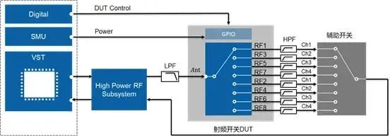
The single-tone radio frequency signal generated by VST is amplified by NI's high-power module (NI 5534), and the output power can reach 38dBm. The amplified signal is filtered by low-pass filter to the device under test. After filtering out the main frequency component of the output signal of the device under test, the remaining harmonic component is sent to the receiving path of NI high-power module (NI 5534) through the auxiliary switch. After attenuation, it is fed into VST.