1. Audio test
Audio system is a complex system, which needs comprehensive consideration from product positioning, circuit design, structural design, material selection, horn selection, sound cavity design and other aspects. After the preliminary design is completed, it is also necessary to use professional equipment or go to a professional acoustic laboratory for audio related tests: basic acoutoelectric tests; Sound quality testing; Sound power test; Product vibration test and noise test.
According to product positioning and test results, the hardware and software design and parameters are repeatedly adjusted to achieve a relatively satisfactory acoustic effect. It is a complicated and lengthy process.
1.1 Basic electroacoustic test
Basic electroacoustic test is the most basic test in audio system testing, which generally includes frequency response (FR); Total harmonic distortion (THD); Signal-to-noise ratio (SNR) and sound pressure level (SPL). Of course, the index can be increased or decreased according to needs.
Basic acousti-electric test quantifies some basic indicators of acoustic system, which can reflect the most basic quality of an audio system. An acoustic system with qualified basic acoustic and electrical indicators is a good acoustic system, but an acoustic system if even the basic acoustic and electrical indicators are very bad, it must not be an excellent acoustic system.
1.2 Test Indicators
In basic acoustoelectricity, a more important index is the total harmonic distortion (THD).
The total harmonic distortion shows that when the power amplifier works, due to the second and third harmonics generated by the inevitable oscillation or other resonance of the circuit and the actual input signal superposition, the output signal is not simply the same component as the input signal, but includes the harmonic component of the signal, and the contrast between these excess harmonic components and the actual input signal, Expressed in percentage terms, it is called total harmonic distortion.
The THD of the general acoustic system is 2% ~ 3%; Below 1% it's almost undistinguishable to the human ear.
1.3 Test Method
Closed-loop testing is generally adopted, and open-loop testing can also be used as a reference when closed-loop testing is not possible.
Closed-loop test generally has Bluetooth transmission, AUX interface transmission, LINN/LINP port input. The latter two inputs are preferred because the Bluetooth module also has the potential to cause distortion overlay.
1.4 Examples
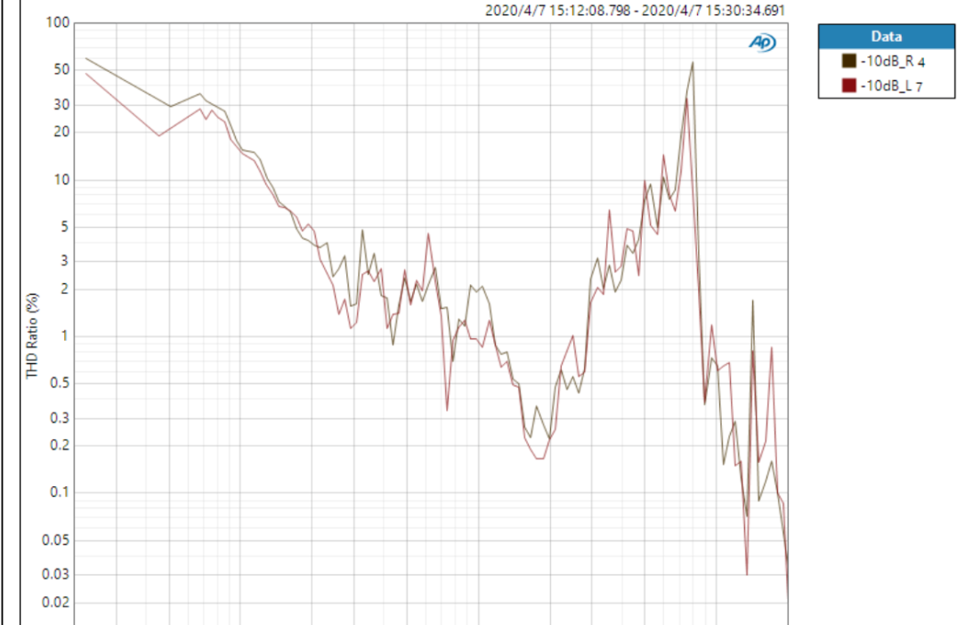
The figure below shows the total harmonic distortion (THD) of a real audiosystem with -10dB input. It can be seen that the low frequency part below 200Hz and the part around 8KHz are very high THD, more than 50%. In other frequency bands, THD can basically remain below 5%. As you can see from the figure, there is a lot of room for improvement in this audio system.
2. Analysis framework
The overall distortion of an audio system can be seen as a superposition of the distortion of three parts. These three parts can generally be divided into: circuit distortion, structure distortion and horn distortion.
2.1 Circuit Distortion
Circuit distortion refers to: audio signal in the circuit transmission, conversion process of electromagnetic interference, conversion device distortion and resonance and other causes of distortion.
The circuit distortion is generally not more than 3%, and the qualified circuit distortion is generally less than 0.5%. For class D digital power amplifiers, burrs (high-frequency harmonics) belong to this type of power amplifier characteristics, basically can not be eliminated, do not affect the use of can be ignored.
2.2 Structural distortion
Structural distortion refers to the reflection, resonance and other distortion caused by the structural design problems of the sound cavity, the front shell and even the whole product.
For reflection, resonance distortion due to the structure, if the frequency band is very narrow, or even single-frequency distortion, it can be ignored. Because normal use is almost imperceptible to the human ear. But broadband distortion needs to be dealt with carefully.
2.3 Horn distortion
Horn distortion refers to the sound distortion of the horn in the process of acoustoelectric conversion, which is determined by the structure of the horn, electromagnetic properties, materials and so on.
3.1 Circuit Distortion
At the output end, a two-stage filter is used, preferably a π filter or an inverted L filter (2nF+470pF+uH).
3.2 Structural distortion
Modifications without changing the structure:
For reflection distortion: add absorbent cotton to the sound cavity; Add soft rubber ring.
For resonance: Add damping film at the resonance point.
Changes to the structure:
The bottom of the cavity should be designed as large as possible (avoid right angles, preferably spherical).
The front cavity should not be too large, too deep.
The sound volume of the cavity is twice that of the horn
3.3 Speaker distortion
The speaker has almost no response below the low frequency part (200Hz), so a filter can be used on the circuit to completely remove the audio below 200Hz, which can make the sound quality more pure.